Sharp MXM620U�������ϴ�������,Ӣ���ֲ�02
�ۺ�绰696l6769,ά���ѯ,�ۺ����,����ά��,��������,�ͻ�����,ά���ֲ�,�û��ֲ�
�ֳ�ά��չʾ1 
�ֳ�ά��չʾ2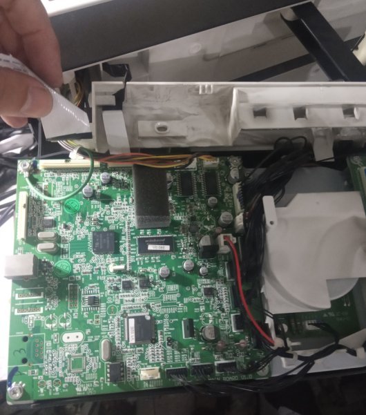
�ֳ�ά��չʾ3 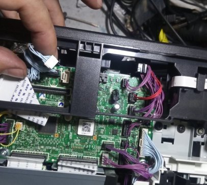
Code: F2-39
Description:
Process thermistor breakdown
When the input value of the process thermistor is detected as 235 or greater or 22 or smaller for 3 times continuously.
Causes:
Improper connection of the process thermistor harness.
Process thermistor trouble
PCU PWB trouble
Remedy:
Case 1 Cause Improper connection of the process thermistor harness. Check and remedy Check connection of the connector and the harness of the process thermistor. Case 2 Cause Process thermistor trouble Check and remedy Check the process thermistor. Case 3 Cause PCU PWB trouble Check and remedy Check the PCU PWB.
Code: F2-46
Description:
Developing thermistor breakdown
When the input value of the process thermistor is detected as 244 or greater or 20 or smaller for 3 times continuously
Causes:
Developing thermistor harness connection trouble
Developing thermistor harness trouble
PCU PWB trouble
Remedy:
Case 1 Cause Developing thermistor harness connection trouble Check and remedy Check connection of the connector and the harness of the developing thermistor. Case 2 Cause Developing thermistor harness trouble Check and remedy Check the developing thermistor Case 3 Cause PCU PWB trouble Check and remedy Check the PCU PWB.
Code: F2-47
Description:
Room temperature thermistor breakdown
When the input value of the process thermistor is detected as 235 or greater or 22 or smaller for 3 times continuously.
Causes:
Improper connection of the room temperature thermistor harness.
Room temperature thermistor trouble
PCU PWB trouble
Remedy:
Case 1 Cause Improper connection of the room temperature thermistor harness. Check and remedy Check connection of the connector and the harness of the process thermistor. Case 2 Cause Room temperature thermistor trouble Check and remedy Check the room temperature thermistor. Case 3 Cause PCU PWB trouble Check and remedy Check the PCU PWB.
Code: F2-48
Description:
Developing humidity sensor break down
When the output value of the development humidity sensor is detected as 38 or smaller or 255 or greater. The output value is the average value of 5 sampling data in the interval of 100ms.
Causes:
Developing humidity sensor harness connection trouble
Developing humidity sensor trouble
PCU PWB trouble
Remedy:
Case 1 Cause Developing humidity sensor harness connection trouble Check and remedy Check connection of the connector and the harness of the developing humidity sensor. Case 2 Cause Developing humidity sensor trouble Check and remedy Check the developing humidity sensor Case 3 Cause PCU PWB trouble Check and remedy Check the PCU PWB.
Code: F3-12
Description:
Machine tray 1 lift-up trouble
PED does not turn on within the specified time. LUD does not turn on within the specified time. The trouble occurs 3 times continuously that the upper limit sensor does not turn on by lift-up operation for 21sec when inserting a tray or for 2sec when printing. For the first and the second times, guide the user to pull out the tray in case of a tray size error.
Causes:
PED, LUD trouble No. 1 tray lift-up motor trouble Improper connection of the harness of the PCU PWB, the lift-up unit, and the paper feed unit
Remedy:
Check the harness and connector of PED and LUD Lift-up trouble unit check. Use SIM 15 to cancel the trouble.
Code: F3-22
Description:
Machine tray 2 lift-up trouble
MCPED does not turn on within the specified time. MCLUD does not turn on within the specified time. The trouble occurs 3 times continuously that the upper limit sensor does not turn on by lift-up operation for 21sec when inserting a tray or for 2sec when printing. For the first and the second times, guide the user to pull out the tray in case of a tray size error.
Causes:
MCPED, MCLUD trouble No. 2 tray lift-up motor trouble Improper connection of the harness of the PCU PWB, the lift-up unit, and the paper feed unit
Remedy:
Check the harness and the connector of MCPED and MCLUD. Lift-up trouble unit check. Use SIM 15 to cancel the trouble.
Code: F3-32
Description:
Machine tray 3 lift-up trouble
MCPED does not turn on within the specified time. MCLUD does not turn on within the specified time. The trouble occurs 3 times continuously that the upper limit sensor does not turn on by lift-up operation for 10sec when inserting a tray or for 2sec when printing. For the first and the second times, guide the user to pull out the tray in case of a tray size error.
Causes:
MCPED, MCLUD trouble No. 3 tray lift-up motor trouble Improper connection of the harness of the PCU PWB, the lift-up unit, and the paper feed unit
Remedy:
Check the harness and the connector of MCPED and MCLUD. Lift-up trouble unit check
Code: F3-42
Description:
Machine tray 4 lift-up trouble
MCPED does not turn on within the specified time. MCLUD does not turn on within the specified time. The trouble occurs 3 times continuously that the upper limit sensor does not turn on by lift-up operation for 10sec when inserting a tray or for 2sec when printing. For the first and the second times, guide the user to pull out the tray in case of a tray size error.
Causes:
MCPED, MCLUD trouble No. 4 tray lift-up motor trouble. Improper connection of the harness of the PCU PWB, the lift-up unit, and the paper feed unit.
Remedy:
Check the harness and the connector of MCPED and MCLUD. Lift-up trouble unit check.
Code: F4-38
Description:
38V voltage trouble
38V voltage falls or rises. When the 38V MON signal is not turned on in 50ms after turning on the INTRP.
Causes:
Improper connection or disconnection of the connector and the harness
PCU PWB trouble Power unit trouble
Remedy:
Case 1 Cause Improper connection or disconnection of the connector and the harness Check and remedy Check the connector and the harness of the power line. Case 2 Cause PCU PWB trouble Power unit trouble Check and remedy Check 38V power source in the power unit and the PCU PWB.
Code: F6-00
Description:
MFP control-FAX communication trouble (MFP control detection)
The booting sequence by the command line (9600bps, serial) is not completed normally. Communication establishment error/ framing/ parity/protocol error
Causes:
Defective connection of the slave unit PWB connector. Defective harness between the slave unit PWB and the MFP control PWB. Slave unit PWB mother board connector pin breakage.
Slave unit ROM trouble/no ROM/ Reversed
insertion of ROM/ ROM pin breakage
Remedy:
Case 1 Cause Defective connection of the slave unit PWB connector. Defective harness between the slave unit PWB and the MFP control PWB. Slave unit PWB mother board connector pin breakage. Check and remedy Check connection of the connector between the slave unit PWB and the MFP control PWB and the harness. Case 2 Cause Slave unit ROM trouble/no ROM/ Reversed insertion of ROM/ ROM pin breakage Check and remedy Check the ROM on the slave unitPWB.
Code: F6-01
Description:
FAX Flash memory trouble (MFP control detection)
The flash memory inserted to the FAX I/F PWB could not be cleared.
Causes:
The flash memory could not be cleared.
Remedy:
FAX image save flash memory check. Use SIM 66-10 to clear the expansion flash memory.
Code: F6-04
Description:
FAX modem operation abnormality
The initializing process of the modem chip in the FAX PWB is not completed normally.
Causes:
SW101 in the FAX PWB tries to perform normal operation on the boot side.
FAX PWB modem chip operation trouble
Remedy:
Case 1 Cause SW101 in the FAX PWB tries to perform normal operation on the boot side. Check and remedy Set SW101 on the FAX PWB to other than the boot side, and turn on the power again. Case 2 Cause FAX PWB modem chip operation trouble Check and remedy Replace the FAX PWB.
Code: F6-20
Description:
FAX write protect cancel
The write protect jumper of the FAX interface PWB is released.
Causes:
The FAX write protect pin is set to Write Enable.
FAX interface PWB trouble FAX PWB trouble
Remedy:
Case 1 Cause The FAX write protect pin is set to Write Enable. Check and remedy Check the write protect pin in the FAX interface PWB. Case 2 Cause FAX interface PWB trouble FAX PWB trouble Check and remedy Replace the FAX PWB. Replace the FAX interface PWB.
Code: F6-21
Description:
Abnormal combination of the TEL/LIU PWB and the FAX soft switch
Combination error of TEL/LIU PWB and software If the destination of the installed TEL/LIU PWB differs from that of the FAX soft switch, it is judged as an error. Or when the TEL/LIU PWB is not a new one for a new MDMC PWB.
Causes:
The destination of the installed TEL/LIU PWB differs. The FAX PWB information (soft switch) differs.
TEL/LIU PWB trouble
The TEL/LIU PWB is not a new one.
Remedy:
Case 1 Cause The destination of the installed TEL/LIU PWB differs. The FAX PWB information (soft switch) differs. Check and remedy Check the destination of the TEL/LIU PWB. Check the FAX PWB information (soft switch). Case 2 Cause TEL/LIU PWB trouble Check and remedy Replace the TEL/LIU PWB. Case 3 Cause The TEL/LIU PWB is not a new one. Check and remedy Replace the TEL/LIU PWB with a new one.
Code: F6-97
Description:
FAX-BOX incompatibility trouble
The FAX-BOX PWB is not one for the main unit. (FAX detection) If the FAX-BOX modem controller PWB information (hard detection) is not for the main unit, it is judged as an error.
Causes:
Because the FAX-BOX modem controller PWB information (hard detection) is not for the main unit.
Remedy:
Check the FAX-BOX modem controller PWB. Replace it with a modem controller PWB for the main unit.
Code: F6-98
Description:
Combination error of the FAX-BOX destination information and the machine destination information
When the destination information stored in the FAX-BOX EEPROM is compared with that of the machine, and if the combination is improper, it is judged as an error.
Causes:
Because of improper combination between the destination information stored in the EEPROM on the FAX-BOX PWB and that of the machine (set with SIM 26-6).
Remedy:
Check the destination of the FAX-BOX. Check the machine destination with SIM 26-6. Use a proper combination of the machine and the FAX-BOX.
Code: F7-01
Description:
FAX board EEPROM read/write error
ACK from the EEPROM cannot be checked.
Causes:
EEPROM trouble FAX PWB EEPROM access circuit trouble
Remedy:
Replace the EEPROM. Re-setup the soft SW.
Code: H2-00
Description:
Thermistor open/Fusing unit not installed (HL1)
Thermistor open (An input voltage of 4.6V or above is detected.) Fusing unit not installed
Causes:
Thermistor trouble. Control PWB trouble Improper connection of the fusing section connector. AC power trouble. Fusing unit not installed.
Remedy:
Check the harness and the connector between the thermistor and the control PWB. Use SIM 14 to clear the self diag display.
Code: H2-01
Description:
Thermistor open/Fusing unit not installed (HL2)
Thermistor open (An input voltage of 4.6V or above is detected.) Fusing unit not installed
Causes:
Thermistor trouble Control PWB trouble Improper. connection of the fusing section connector. AC power trouble. Fusing unit not installed.
Remedy:
Check the harness and the connector between the thermistor and the control PWB. Use SIM 14 to clear the self diag display.
Code: H2-02
Description:
Thermistor open/Fusing unit not installed (HL3)
Thermistor open (An input voltage of 4.6V or above is detected.) Fusing unit not installed
Causes:
Thermistor trouble. Control PWB trouble. Improper connection of the fusing section connector. AC power trouble. Fusing unit not installed.
Remedy:
Check the harness and the connector between the thermistor and the control PWB. Use SIM 14 to clear the self diag display.
Code: H3-00
Description:
Fusing section high temperature trouble (HL1)
The fusing temperature exceeds 241.5 �C. (An input voltage of 1.3V or less is detected.) When fusing temperature control is started and a temperature of 242 �C is detected 3 times continuously in sampling of 250 msec interval. (In the interval of 150ms)
Causes:
Thermistor trouble Control PWB trouble Improper connection of the fusing section connector AC power trouble
Remedy:
Use SIM 5-2 to check flashing of the heater lamp. When the lamp flashes normally. ?Check the thermistor and the harness. ?Check the thermistor input circuit on the control PWB. When the lamp keeps ON. ?Check the AC PWB and the lamp control circuit on the control PWB. Use SIM 14 to cancel the trouble
Code: H3-01
Description:
Fusing section high temperature trouble (HL2)
The fusing temperature exceeds 241.5 �C. (An input voltage of 1.3V or less is detected.) When fusing temperature control is started and a temperature of 242 �C is detected 3 times continuously in sampling of 250 msec interval. (In the interval of 150ms)
Causes:
Thermistor trouble. Control PWB trouble.
Improper connection of the fusing section
connector. AC power trouble.
Remedy:
Use SIM 5-2 to check flashing of the heater lamp. When the lamp flashes normally. ?Check the thermistor and the harness. ?Check the thermistor input circuit on the control PWB. When the lamp keeps ON. ?Check the AC PWB and the lamp control circuit on the control PWB. Use SIM 14 to cancel the trouble
Code: H3-02
Description:
Fusing section high temperature trouble (HL3)
The fusing temperature exceeds 241.5 �C. (An input voltage of 1.3V or less is detected.) When fusing temperature control is started and a temperature of 242 �C is detected 3 times continuously in sampling of 250 msec interval. (In the interval of 150ms)
Causes:
Thermistor trouble Control PWB trouble Improper connection of the fusing section connector AC power trouble
Remedy:
Use SIM 5-2 to check flashing of the heater lamp. When the lamp flashes normally. ?Check the thermistor and the harness. ?Check the thermistor input circuit on the control PWB. When the lamp keeps ON. ?Check the AC PWB and the lamp control circuit on the control PWB. Use SIM 14 to cancel the trouble
Code: H4-00
Description:
Fusing section low temperature trouble (HL1)
The set temperature is not reached within the specified time (normally 3 min or 5 min in the curl prevention mode) after turning on the power relay. When the heater lamp is not turned off in 4 min after starting the warm-up operation. When the set value of -40�C is detected for 5 times continuously in the specified interval after completion of the warm-up operation. (In the interval of 150ms)
Causes:
Thermistor trouble Heater lamp trouble
Control PWB trouble Thermostat trouble
AC power trouble Interlock switch
Remedy:
Use SIM 5-2 to check flashing of the heater lamp. When the lamp flashes normally. ?Check the thermistor and the harness. ?Check the thermistor input circuit on the control PWB. When the lamp does not turn on. ?Check for disconnection of the heater lamp or the thermostat. ?Check the interlock switch. ?Check the AC PWB and the lamp control circuit on the control PWB. Use SIM 14 to cancel the trouble
Code: H4-01
Description:
Fusing section low temperature trouble (HL2)
The set temperature is not reached within the specified time (normally 3 min or 5 min in the curl prevention mode) after turning on the power relay. When the heater lamp is not turned off in 4 min after starting the warm-up operation. When the set value of -40�C is detected for 5 times continuously in the specified interval after completion of the warm-up operation. (In the interval of 150ms)
Causes:
Thermistor trouble Heater lamp trouble
Control PWB trouble Thermostat trouble
AC power trouble Interlock switch
Remedy:
Use SIM 5-2 to check flashing of the heater lamp. When the lamp flashes normally. ?Check the thermistor and the harness. ?Check the thermistor input circuit on the control PWB. When the lamp does not turn on. ?Check for disconnection of the heater lamp or the thermostat. ?Check the interlock switch. ?Check the AC PWB and the lamp control circuit on the control PWB. Use SIM 14 to cancel the trouble
Code: H4-02
Description:
Fusing section low temperature trouble (HL3)
The set temperature is not reached within the specified time (normally 3 min or 5 min in the curl prevention mode) after turning on the power relay. When the heater lamp is not turned off in 4 min after starting the warm-up operation. When the set value of -40�C is detected for 5 times continuously in the specified interval after completion of the warm-up operation. (In the interval of 150ms)
Causes:
Thermistor trouble Heater lamp trouble Control PWB trouble Thermostat trouble AC power trouble Interlock switch
Remedy:
Use SIM 5-2 to check flashing of the heater lamp. When the lamp flashes normally. ?Check the thermistor and the harness. ?Check the thermistor input circuit on the control PWB. When the lamp does not turn on. ?Check for disconnection of the heater lamp or the thermostat. ?Check the interlock switch. ?Check the AC PWB and the lamp control circuit on the control PWB. Use SIM 14 to cancel the trouble
Code: H5-01
Description:
5-times continuous POD notreached JAM detection
When POD1 not-reached jam is detected 5-times continuously. POD1 jam counter is backed up and used in a print job after turning on the power. The counter is cleared when POD1 jam does not occur in a job or when the trouble is canceled.
Causes:
The fusing jam is not canceled completely. (Jam paper remains.)
POD1 sensor trouble, or harness connection trouble
Fusing unit installation trouble
Remedy:
Case 1 Cause The fusing jam is not canceled completely. (Jam paper remains.) Check and remedy Check for jam paper in the fusing section. (Winding, etc.) Case 2 Cause POD1 sensor trouble, or harness connection trouble Check and remedy Check the PODC1 sensor harness and installation of the fusing unit. Case 3 Cause Fusing unit installation trouble Check and remedy Use SIM 14 to cancel the trouble
Code: L1-00
Description:
Scanner feed trouble
Scanner feed is not completed within the specified time. When Mhp Soft is not detected within 2 sec after shifting the mirror base unit in the feeding direction.
Causes:
Scanner unit trouble The scanner wire is disconnected.
Remedy:
Use SIM 1-1 to check scanning operation.
Code: L3-00
Description:
Scanner return trouble
Scanner return is not completed within the specified time. MhpSon is not detected within 10sec after starting the mirror base unit in the return direction.
Causes:
Scanner unit trouble The scanner wire is disconnected.
Remedy:
Use SIM 1-1 to check scanning operation.
Code: L4-01
Description:
Main motor lock detection
When it is detected for 3 times continuously in the interval of 500ms after ignoring the main motor drive for 600ms.
Causes:
Main motor trouble
Improper disconnection of the harness between the PCU PWB and the main motor Control circuit trouble
Remedy:
Case 1 Cause Main motor trouble Check and remedy Use SIM 25-1 to check the main motor operation. Case 2 Cause Improper disconnection of the harness between the PCU PWB and the main motor Control circuit trouble Check and remedy Check the harness and the connector between the PCU PWB and the main motor.
Code: L4-02
Description:
Drum motor lock detection
The motor lock signal is detected for 1.5sec during rotation of the drum motor. When the motor lock signal is detected for 3 times continuously in the interval of 500ms after 900ms of rotation start.
Causes:
Drum motor trouble
Improper connection of the harness between the PCU PWB and the drum motor Control circuit trouble
Remedy:
Case 1 Cause Drum motor trouble Check and remedy Use SIM 25-1 to check the drum motor operation. Case 2 Cause Improper connection of the harness between the PCU PWB and the drum motor Control circuit trouble Check and remedy Check the harness and the connector of the PCU PWB, and the drum motor.
Code: L4-03
Description:
Fusing motor lock detection
When it is detected for 3 times continuously in the interval of 500ms after ignoring the fusing motor drive start for 600ms.
Causes:
Main motor troubleI
mproper connection of the harness between the PCU PWB and the fusing motor Control circuit trouble
Remedy:
Case 1 Cause Main motor trouble Check and remedy Use SIM 25-1 to check the fusing motor operation. Case 2 Cause Improper connection of the harness between the PCU PWB and the fusing motor Control circuit trouble Check and remedy Check connection of the harness and the connector between the PCU PWB and the fusing motor.
Code: L4-04
Description:
Developing motor lock detection
The motor lock signal is detected for 1.5sec during rotation of the developing motor. When the motor lock signal is detected for 3 times continuously in the interval of 500ms after 900ms of rotation start.
Causes:
Developing motor trouble
Improper connection of the harness between the PCU PWB and the developing motor. Control circuit trouble.
Remedy:
Case 1 Cause Developing motor trouble Check and remedy Use SIM 6-1 to check the developing motor operation. Case 2 Cause Improper connection of the harness between the PCU PWB and the developing motor. Control circuit trouble. Check and remedy Check the harness and the connector between the PCU PWB and the developing motor.
Code: L4-06
Description:
Transfer belt separation motor trouble detection
Transfer belt separation motor trouble detection The transfer belt home position sensor ON/OFF is not detected within the specified time (4 sec) during operation of the transfer belt (separation, contact).
Causes:
Transfer belt separation motor trouble
Improper connection of the harness between the PCU PWB and the transfer belt separation motor. Control circuit trouble
Remedy:
Case 1 Cause Transfer belt separation motor trouble Check and remedy Use SIM 6-1 to check the transfer belt motor operation. Case 2 Cause Improper connection of the harness between the PCU PWB and the transfer belt separation motor. Control circuit trouble Check and remedy Check connection of the harness and the connection of the harness between the PCU PWB and the transfer belt separation motor.
Code: L4-30
Description:
Controller fan motor lock detection
The motor lock signal is detected during rotation of the controller fan motor. The motor lock signal is detected during rotation of the HDD fan motor.
Causes:
Fan motor trouble
Improper connection of the harness between the controller PWB and the fan motor. Control circuit trouble
Remedy:
Case 1 Cause Fan motor trouble Check and remedy Use SIM 6-2 to check the fan motor operation. Case 2 Cause Improper connection of the harness between the controller PWB and the fan motor. Control circuit trouble Check and remedy Check the harness and the connector between the controller PWB and the fan motor.
Code: L4-31
Description:
Paper discharging fan trouble
When the detected value of the temperature sensor (TH_EX) in the paper exit reverse unit is greater than the specified level for 2 times continuously in the interval of 30sec. When 100�C (value of 235) of the paper exit thermistor is detected for 3 times continuously. (In the interval of 100ms)
Causes:
Fan motor trouble
PCU PWB, harness connection between fan and motor trouble PCU circuit trouble
Thermistor (TH_EX) trouble
Remedy:
Case 1 Cause Fan motor trouble Check and remedy Use SIM 6-2 to check the fan motor operation. Case 2 Cause PCU PWB, harness connection between fan and motor trouble PCU circuit trouble Thermistor (TH_EX) trouble Check and remedy Check the PCU PWB, the harness between fan and motor, and the connector.
Code: L6-10
Description:
Polygon motor lock detection
It is judged that the polygon motor lock signal of the LSU is not outputted. The polygon motor lock signal is checked in an interval of 10sec after starting the polygon motor, and it is found that the olygon motor is not rotating normally.
Causes:
Polygon motor trouble
Disconnection or breakage of the LSU connector or the harness in the LSU
Remedy:
Case 1 Cause Polygon motor trouble Check and remedy Use SIM 61-1 to check the polygon motor operation. Case 2 Cause Disconnection or breakage of the LSU connector or the harness in the LSU Check and remedy Check connection of the harness and the connector. Replace the LSU.
Code: L8-01
Description:
No full wave signal
The full wave signal is not detected. When the FWS signal is not varied for 120ms when supplying the power.
Causes:
Disconnection or breakage of the PCU PWB connector or the harness in the power unit
PCU PWB trouble
12V power source trouble
Remedy:
Case 1 Cause Disconnection or breakage of the PCU PWB connector or the harness in the power unit Check and remedy Check connection of the harness and the connector. Case 2 Cause PCU PWB trouble Check and remedy Replace the PCU PWB. Case 3 Cause 12V power source trouble Check and remedy Replace the power unit. Replace the controller connection mother board.
Code: PF-00
Description:
RIC copy inhibit command receive
The copy inhibit command is received from the RIC (host). (By PPC communication standards.)
Causes:
Judged by the host.
Remedy:
Notification to the host
Code: U1-01
Description:
FAX battery abnormality
FAX backup SRAM battery voltage fall. When the battery capacity is less than the threshold value (fixed by the hardware), it is judged as an error. (Insufficient capacity of the SRAM backup battery)
Causes:
Battery life
Battery circuit trouble
Remedy:
Case 1 Cause Battery life Check and remedy Check that the battery voltage is about 2.5V or above. Case 2 Cause Battery circuit trouble Check and remedy Check the battery circuit.
Code: U1-02
Description:
RTC read error (combined use as FAX, on MFP control PWB)
The read value from the RTC on the MFP control PWB is abnormal such as "EE"h.
Causes:
RTC circuit trouble
Battery voltage fall
Battery circuit trouble
Remedy:
Case 1 Cause RTC circuit trouble Check and remedy Make the time setup again with the key operation and check that the time advances normally. Check the RTC circuit. Case 2 Cause Battery voltage fall Check and remedy Check that the battery voltage is about 2.5V or above. Case 3 Cause Battery circuit trouble Check and remedy Check the battery circuit.
Code: U2-00
Description:
EEPROM read/write error (MFP control)
EEPROM write error (without retry) EEPROM magic number error.
Causes:
EEPROM trouble
Insertion of EEPROM which is not initialized
MFP control PWB EEPROM access circuit trouble
Remedy:
Case 1 Cause EEPROM trouble Check and remedy Check that the EEPROM is properly installed. In the simulation to prevent against delete of the counter data/adjustment values, write down the counter/adjustment values. Case 2 Cause Insertion of EEPROM which is not initialized Check and remedy Use SIM 16 to cancel the U2 trouble. Case 3 Cause MFP control PWB EEPROM access circuit trouble Check and remedy Replace the MFP control PWB.
Code: U2-11
Description:
Counter check sum error (MFP control)
EEPROM counter area checksum error. (If this error occurs, the process will retrieve for effective data within 8 blocks.)
Causes:
EEPROM trouble
Control circuit runaway due to noises
MFP control PWB EEPROM access circuit trouble
Remedy:
Case 1 Cause EEPROM trouble Check and remedy Check that the EEPROM is properly installed. In the simulation to prevent against delete of the counter data/adjustment values, write down the counter/adjustment values. Case 2 Cause Control circuit runaway due to noises Check and remedy Use SIM 16 to cancel the U2 trouble. Case 3 Cause MFP control PWB EEPROM access circuit trouble Check and remedy Replace the MFP control PWB.
Code: U2-12
Description:
Adjustment value check sum error (MFP control)
EEPROM counter area checksum error (If this error occurs, the process will retrieve for effective data within 8 blocks.)
Causes:
EEPROM trouble
Control circuit runaway due to noises
MFP control PWB EEPROM access circuit trouble
Remedy:
Case 1 Cause EEPROM trouble Check and remedy Check that the EEPROM is properly installed. In the simulation to prevent against delete of the counter data/adjustment values, write down the counter/adjustment values. Case 2 Cause Control circuit runaway due to noises Check and remedy Use SIM 16 to cancel the U2 trouble. Case 3 Cause MFP control PWB EEPROM access circuit trouble Check and remedy Replace the MFP control PWB.
Code: U2-22
Description:
SRAM memory check sum error (MFP control)
SRAM check sum error when turning on the power. (If this error occurs, initialize the one-touch dial and the FAX soft switches.)
Causes:
SRAM trouble
Control circuit runaway due to noises
MFP control PWB EEPROM access circuit trouble
Remedy:
Case 1 Cause SRAM trouble Check and remedy Initialize the communication management table registered in the SRAM and the FAX soft switch. Since the registered data are deleted, register the data again. Case 2 Cause Control circuit runaway due to noises Check and remedy Use SIM 16 to cancel the U2 trouble. Case 3 Cause MFP control PWB EEPROM access circuit trouble Check and remedy Replace the MFP control PWB.
Code: U2-23
Description:
SRAM memory individual data check sum error
Check sum error for every individual data in SRAM of the MFPC section when turning on the power (If this error occurs, initialize the data related to the check sum error. (Communication management table, sender's information, etc.))
Causes:
SRAM trouble
Control circuit runaway due to noises
MFP control PWB EEPROM access circuit trouble
Remedy:
Case 1 Cause SRAM trouble Check and remedy Automatically initialize the data related to the check sum error by turning OFF/ON the power. Since the registered data are deleted, register the data again. Case 2 Cause Control circuit runaway due to noises Check and remedy Use SIM 16 to cancel the U2 trouble. Case 3 Cause MFP control PWB EEPROM access circuit trouble Check and remedy Replace the MFP control PWB.
Code: U2-50
Description:
HDD section individual data check sum error (MFP control)
Check sum error for every individual data in HDD of the MFPC section when turning on the power
(If this error occurs, initialize the data related to the check sum error. (One-touch, group, program, etc.))
Causes:
HDD write/read error
Control circuit runaway due to noises
MFP control PWB HDD access circuit trouble
Remedy:
Case 1 Cause HDD write/read error Check and remedy Automatically initialize the data related to the check sum error by turning OFF/ON the power. Since the registered data are deleted, register the data again. Case 2 Cause Control circuit runaway due to noises Check and remedy Use SIM 16 to cancel the U2 trouble. Case 3 Cause MFP control PWB HDD access circuit trouble Check and remedy Replace the HDD. Replace the MFP control PWB.
Code: U2-80
Description:
EEPROM read/write error (Scanner)
EEPROM communication trouble (NACK detection) Retry 3 times
Causes:
EEPROM trouble
Insertion of EEPROM which is not initialized
Scanner PWB EEPROM access circuit trouble
Remedy:
Case 1 Cause EEPROM trouble Check and remedy Check that the EEPROM is properly installed. In the simulation to prevent against delete of the counter data/adjustment values, write down the counter/adjustment values. Case 2 Cause Insertion of EEPROM which is not initialized Check and remedy Use SIM 16 to cancel the U2 trouble. Case 3 Cause Scanner PWB EEPROM access circuit trouble Check and remedy Replace the scanner PWB.
Code: U2-81
Description:
Memory check sum error (Scanner)
When counter data sum error is detected.
Causes:
EEPROM trouble
Control circuit runaway due to noises
Scanner PWB EEPROM access circuit trouble
Remedy:
Case 1 Cause EEPROM trouble Check and remedy Check that the EEPROM is properly installed. In the simulation to prevent against delete of the counter data/adjustment values, write down the counter/adjustment values. Case 2 Cause Control circuit runaway due to noises Check and remedy Use SIM 16 to cancel the U2 trouble. Case 3 Cause Scanner PWB EEPROM access circuit trouble Check and remedy Replace the scanner PWB.
Code: U2-90
Description:
EEPROM read/write error (PCU)
EEPROM communication trouble (NACK detection) Retry 3 times
Causes:
EEPROM trouble
Insertion of EEPROM which is not initialized
PCU PWB EEPROM access circuit trouble
Remedy:
Case 1 Cause EEPROM trouble Check and remedy Check that the EEPROM is properly installed. In the simulation to prevent against delete of the counter data/adjustment values, write down the counter/adjustment values. Case 2 Cause Insertion of EEPROM which is not initialized Check and remedy Use SIM 16 to cancel the U2 trouble. Case 3 Cause PCU PWB EEPROM access circuit trouble Check and remedy Replace the PCU PWB.
Code: U2-91
Description:
Memory check sum error (PCU)
When POF data/counter data sum error is detected.
Causes:
EEPROM trouble
Control circuit runaway due to noises
PCU PWB EEPROM access circuit trouble
Remedy:
Case 1 Cause EEPROM trouble Check and remedy Check that the EEPROM is properly installed. In the simulation to prevent against delete o
Description:
Process thermistor breakdown
When the input value of the process thermistor is detected as 235 or greater or 22 or smaller for 3 times continuously.
Causes:
Improper connection of the process thermistor harness.
Process thermistor trouble
PCU PWB trouble
Remedy:
Case 1 Cause Improper connection of the process thermistor harness. Check and remedy Check connection of the connector and the harness of the process thermistor. Case 2 Cause Process thermistor trouble Check and remedy Check the process thermistor. Case 3 Cause PCU PWB trouble Check and remedy Check the PCU PWB.
Code: F2-46
Description:
Developing thermistor breakdown
When the input value of the process thermistor is detected as 244 or greater or 20 or smaller for 3 times continuously
Causes:
Developing thermistor harness connection trouble
Developing thermistor harness trouble
PCU PWB trouble
Remedy:
Case 1 Cause Developing thermistor harness connection trouble Check and remedy Check connection of the connector and the harness of the developing thermistor. Case 2 Cause Developing thermistor harness trouble Check and remedy Check the developing thermistor Case 3 Cause PCU PWB trouble Check and remedy Check the PCU PWB.
Code: F2-47
Description:
Room temperature thermistor breakdown
When the input value of the process thermistor is detected as 235 or greater or 22 or smaller for 3 times continuously.
Causes:
Improper connection of the room temperature thermistor harness.
Room temperature thermistor trouble
PCU PWB trouble
Remedy:
Case 1 Cause Improper connection of the room temperature thermistor harness. Check and remedy Check connection of the connector and the harness of the process thermistor. Case 2 Cause Room temperature thermistor trouble Check and remedy Check the room temperature thermistor. Case 3 Cause PCU PWB trouble Check and remedy Check the PCU PWB.
Code: F2-48
Description:
Developing humidity sensor break down
When the output value of the development humidity sensor is detected as 38 or smaller or 255 or greater. The output value is the average value of 5 sampling data in the interval of 100ms.
Causes:
Developing humidity sensor harness connection trouble
Developing humidity sensor trouble
PCU PWB trouble
Remedy:
Case 1 Cause Developing humidity sensor harness connection trouble Check and remedy Check connection of the connector and the harness of the developing humidity sensor. Case 2 Cause Developing humidity sensor trouble Check and remedy Check the developing humidity sensor Case 3 Cause PCU PWB trouble Check and remedy Check the PCU PWB.
Code: F3-12
Description:
Machine tray 1 lift-up trouble
PED does not turn on within the specified time. LUD does not turn on within the specified time. The trouble occurs 3 times continuously that the upper limit sensor does not turn on by lift-up operation for 21sec when inserting a tray or for 2sec when printing. For the first and the second times, guide the user to pull out the tray in case of a tray size error.
Causes:
PED, LUD trouble No. 1 tray lift-up motor trouble Improper connection of the harness of the PCU PWB, the lift-up unit, and the paper feed unit
Remedy:
Check the harness and connector of PED and LUD Lift-up trouble unit check. Use SIM 15 to cancel the trouble.
Code: F3-22
Description:
Machine tray 2 lift-up trouble
MCPED does not turn on within the specified time. MCLUD does not turn on within the specified time. The trouble occurs 3 times continuously that the upper limit sensor does not turn on by lift-up operation for 21sec when inserting a tray or for 2sec when printing. For the first and the second times, guide the user to pull out the tray in case of a tray size error.
Causes:
MCPED, MCLUD trouble No. 2 tray lift-up motor trouble Improper connection of the harness of the PCU PWB, the lift-up unit, and the paper feed unit
Remedy:
Check the harness and the connector of MCPED and MCLUD. Lift-up trouble unit check. Use SIM 15 to cancel the trouble.
Code: F3-32
Description:
Machine tray 3 lift-up trouble
MCPED does not turn on within the specified time. MCLUD does not turn on within the specified time. The trouble occurs 3 times continuously that the upper limit sensor does not turn on by lift-up operation for 10sec when inserting a tray or for 2sec when printing. For the first and the second times, guide the user to pull out the tray in case of a tray size error.
Causes:
MCPED, MCLUD trouble No. 3 tray lift-up motor trouble Improper connection of the harness of the PCU PWB, the lift-up unit, and the paper feed unit
Remedy:
Check the harness and the connector of MCPED and MCLUD. Lift-up trouble unit check
Code: F3-42
Description:
Machine tray 4 lift-up trouble
MCPED does not turn on within the specified time. MCLUD does not turn on within the specified time. The trouble occurs 3 times continuously that the upper limit sensor does not turn on by lift-up operation for 10sec when inserting a tray or for 2sec when printing. For the first and the second times, guide the user to pull out the tray in case of a tray size error.
Causes:
MCPED, MCLUD trouble No. 4 tray lift-up motor trouble. Improper connection of the harness of the PCU PWB, the lift-up unit, and the paper feed unit.
Remedy:
Check the harness and the connector of MCPED and MCLUD. Lift-up trouble unit check.
Code: F4-38
Description:
38V voltage trouble
38V voltage falls or rises. When the 38V MON signal is not turned on in 50ms after turning on the INTRP.
Causes:
Improper connection or disconnection of the connector and the harness
PCU PWB trouble Power unit trouble
Remedy:
Case 1 Cause Improper connection or disconnection of the connector and the harness Check and remedy Check the connector and the harness of the power line. Case 2 Cause PCU PWB trouble Power unit trouble Check and remedy Check 38V power source in the power unit and the PCU PWB.
Code: F6-00
Description:
MFP control-FAX communication trouble (MFP control detection)
The booting sequence by the command line (9600bps, serial) is not completed normally. Communication establishment error/ framing/ parity/protocol error
Causes:
Defective connection of the slave unit PWB connector. Defective harness between the slave unit PWB and the MFP control PWB. Slave unit PWB mother board connector pin breakage.
Slave unit ROM trouble/no ROM/ Reversed
insertion of ROM/ ROM pin breakage
Remedy:
Case 1 Cause Defective connection of the slave unit PWB connector. Defective harness between the slave unit PWB and the MFP control PWB. Slave unit PWB mother board connector pin breakage. Check and remedy Check connection of the connector between the slave unit PWB and the MFP control PWB and the harness. Case 2 Cause Slave unit ROM trouble/no ROM/ Reversed insertion of ROM/ ROM pin breakage Check and remedy Check the ROM on the slave unitPWB.
Code: F6-01
Description:
FAX Flash memory trouble (MFP control detection)
The flash memory inserted to the FAX I/F PWB could not be cleared.
Causes:
The flash memory could not be cleared.
Remedy:
FAX image save flash memory check. Use SIM 66-10 to clear the expansion flash memory.
Code: F6-04
Description:
FAX modem operation abnormality
The initializing process of the modem chip in the FAX PWB is not completed normally.
Causes:
SW101 in the FAX PWB tries to perform normal operation on the boot side.
FAX PWB modem chip operation trouble
Remedy:
Case 1 Cause SW101 in the FAX PWB tries to perform normal operation on the boot side. Check and remedy Set SW101 on the FAX PWB to other than the boot side, and turn on the power again. Case 2 Cause FAX PWB modem chip operation trouble Check and remedy Replace the FAX PWB.
Code: F6-20
Description:
FAX write protect cancel
The write protect jumper of the FAX interface PWB is released.
Causes:
The FAX write protect pin is set to Write Enable.
FAX interface PWB trouble FAX PWB trouble
Remedy:
Case 1 Cause The FAX write protect pin is set to Write Enable. Check and remedy Check the write protect pin in the FAX interface PWB. Case 2 Cause FAX interface PWB trouble FAX PWB trouble Check and remedy Replace the FAX PWB. Replace the FAX interface PWB.
Code: F6-21
Description:
Abnormal combination of the TEL/LIU PWB and the FAX soft switch
Combination error of TEL/LIU PWB and software If the destination of the installed TEL/LIU PWB differs from that of the FAX soft switch, it is judged as an error. Or when the TEL/LIU PWB is not a new one for a new MDMC PWB.
Causes:
The destination of the installed TEL/LIU PWB differs. The FAX PWB information (soft switch) differs.
TEL/LIU PWB trouble
The TEL/LIU PWB is not a new one.
Remedy:
Case 1 Cause The destination of the installed TEL/LIU PWB differs. The FAX PWB information (soft switch) differs. Check and remedy Check the destination of the TEL/LIU PWB. Check the FAX PWB information (soft switch). Case 2 Cause TEL/LIU PWB trouble Check and remedy Replace the TEL/LIU PWB. Case 3 Cause The TEL/LIU PWB is not a new one. Check and remedy Replace the TEL/LIU PWB with a new one.
Code: F6-97
Description:
FAX-BOX incompatibility trouble
The FAX-BOX PWB is not one for the main unit. (FAX detection) If the FAX-BOX modem controller PWB information (hard detection) is not for the main unit, it is judged as an error.
Causes:
Because the FAX-BOX modem controller PWB information (hard detection) is not for the main unit.
Remedy:
Check the FAX-BOX modem controller PWB. Replace it with a modem controller PWB for the main unit.
Code: F6-98
Description:
Combination error of the FAX-BOX destination information and the machine destination information
When the destination information stored in the FAX-BOX EEPROM is compared with that of the machine, and if the combination is improper, it is judged as an error.
Causes:
Because of improper combination between the destination information stored in the EEPROM on the FAX-BOX PWB and that of the machine (set with SIM 26-6).
Remedy:
Check the destination of the FAX-BOX. Check the machine destination with SIM 26-6. Use a proper combination of the machine and the FAX-BOX.
Code: F7-01
Description:
FAX board EEPROM read/write error
ACK from the EEPROM cannot be checked.
Causes:
EEPROM trouble FAX PWB EEPROM access circuit trouble
Remedy:
Replace the EEPROM. Re-setup the soft SW.
Code: H2-00
Description:
Thermistor open/Fusing unit not installed (HL1)
Thermistor open (An input voltage of 4.6V or above is detected.) Fusing unit not installed
Causes:
Thermistor trouble. Control PWB trouble Improper connection of the fusing section connector. AC power trouble. Fusing unit not installed.
Remedy:
Check the harness and the connector between the thermistor and the control PWB. Use SIM 14 to clear the self diag display.
Code: H2-01
Description:
Thermistor open/Fusing unit not installed (HL2)
Thermistor open (An input voltage of 4.6V or above is detected.) Fusing unit not installed
Causes:
Thermistor trouble Control PWB trouble Improper. connection of the fusing section connector. AC power trouble. Fusing unit not installed.
Remedy:
Check the harness and the connector between the thermistor and the control PWB. Use SIM 14 to clear the self diag display.
Code: H2-02
Description:
Thermistor open/Fusing unit not installed (HL3)
Thermistor open (An input voltage of 4.6V or above is detected.) Fusing unit not installed
Causes:
Thermistor trouble. Control PWB trouble. Improper connection of the fusing section connector. AC power trouble. Fusing unit not installed.
Remedy:
Check the harness and the connector between the thermistor and the control PWB. Use SIM 14 to clear the self diag display.
Code: H3-00
Description:
Fusing section high temperature trouble (HL1)
The fusing temperature exceeds 241.5 �C. (An input voltage of 1.3V or less is detected.) When fusing temperature control is started and a temperature of 242 �C is detected 3 times continuously in sampling of 250 msec interval. (In the interval of 150ms)
Causes:
Thermistor trouble Control PWB trouble Improper connection of the fusing section connector AC power trouble
Remedy:
Use SIM 5-2 to check flashing of the heater lamp. When the lamp flashes normally. ?Check the thermistor and the harness. ?Check the thermistor input circuit on the control PWB. When the lamp keeps ON. ?Check the AC PWB and the lamp control circuit on the control PWB. Use SIM 14 to cancel the trouble
Code: H3-01
Description:
Fusing section high temperature trouble (HL2)
The fusing temperature exceeds 241.5 �C. (An input voltage of 1.3V or less is detected.) When fusing temperature control is started and a temperature of 242 �C is detected 3 times continuously in sampling of 250 msec interval. (In the interval of 150ms)
Causes:
Thermistor trouble. Control PWB trouble.
Improper connection of the fusing section
connector. AC power trouble.
Remedy:
Use SIM 5-2 to check flashing of the heater lamp. When the lamp flashes normally. ?Check the thermistor and the harness. ?Check the thermistor input circuit on the control PWB. When the lamp keeps ON. ?Check the AC PWB and the lamp control circuit on the control PWB. Use SIM 14 to cancel the trouble
Code: H3-02
Description:
Fusing section high temperature trouble (HL3)
The fusing temperature exceeds 241.5 �C. (An input voltage of 1.3V or less is detected.) When fusing temperature control is started and a temperature of 242 �C is detected 3 times continuously in sampling of 250 msec interval. (In the interval of 150ms)
Causes:
Thermistor trouble Control PWB trouble Improper connection of the fusing section connector AC power trouble
Remedy:
Use SIM 5-2 to check flashing of the heater lamp. When the lamp flashes normally. ?Check the thermistor and the harness. ?Check the thermistor input circuit on the control PWB. When the lamp keeps ON. ?Check the AC PWB and the lamp control circuit on the control PWB. Use SIM 14 to cancel the trouble
Code: H4-00
Description:
Fusing section low temperature trouble (HL1)
The set temperature is not reached within the specified time (normally 3 min or 5 min in the curl prevention mode) after turning on the power relay. When the heater lamp is not turned off in 4 min after starting the warm-up operation. When the set value of -40�C is detected for 5 times continuously in the specified interval after completion of the warm-up operation. (In the interval of 150ms)
Causes:
Thermistor trouble Heater lamp trouble
Control PWB trouble Thermostat trouble
AC power trouble Interlock switch
Remedy:
Use SIM 5-2 to check flashing of the heater lamp. When the lamp flashes normally. ?Check the thermistor and the harness. ?Check the thermistor input circuit on the control PWB. When the lamp does not turn on. ?Check for disconnection of the heater lamp or the thermostat. ?Check the interlock switch. ?Check the AC PWB and the lamp control circuit on the control PWB. Use SIM 14 to cancel the trouble
Code: H4-01
Description:
Fusing section low temperature trouble (HL2)
The set temperature is not reached within the specified time (normally 3 min or 5 min in the curl prevention mode) after turning on the power relay. When the heater lamp is not turned off in 4 min after starting the warm-up operation. When the set value of -40�C is detected for 5 times continuously in the specified interval after completion of the warm-up operation. (In the interval of 150ms)
Causes:
Thermistor trouble Heater lamp trouble
Control PWB trouble Thermostat trouble
AC power trouble Interlock switch
Remedy:
Use SIM 5-2 to check flashing of the heater lamp. When the lamp flashes normally. ?Check the thermistor and the harness. ?Check the thermistor input circuit on the control PWB. When the lamp does not turn on. ?Check for disconnection of the heater lamp or the thermostat. ?Check the interlock switch. ?Check the AC PWB and the lamp control circuit on the control PWB. Use SIM 14 to cancel the trouble
Code: H4-02
Description:
Fusing section low temperature trouble (HL3)
The set temperature is not reached within the specified time (normally 3 min or 5 min in the curl prevention mode) after turning on the power relay. When the heater lamp is not turned off in 4 min after starting the warm-up operation. When the set value of -40�C is detected for 5 times continuously in the specified interval after completion of the warm-up operation. (In the interval of 150ms)
Causes:
Thermistor trouble Heater lamp trouble Control PWB trouble Thermostat trouble AC power trouble Interlock switch
Remedy:
Use SIM 5-2 to check flashing of the heater lamp. When the lamp flashes normally. ?Check the thermistor and the harness. ?Check the thermistor input circuit on the control PWB. When the lamp does not turn on. ?Check for disconnection of the heater lamp or the thermostat. ?Check the interlock switch. ?Check the AC PWB and the lamp control circuit on the control PWB. Use SIM 14 to cancel the trouble
Code: H5-01
Description:
5-times continuous POD notreached JAM detection
When POD1 not-reached jam is detected 5-times continuously. POD1 jam counter is backed up and used in a print job after turning on the power. The counter is cleared when POD1 jam does not occur in a job or when the trouble is canceled.
Causes:
The fusing jam is not canceled completely. (Jam paper remains.)
POD1 sensor trouble, or harness connection trouble
Fusing unit installation trouble
Remedy:
Case 1 Cause The fusing jam is not canceled completely. (Jam paper remains.) Check and remedy Check for jam paper in the fusing section. (Winding, etc.) Case 2 Cause POD1 sensor trouble, or harness connection trouble Check and remedy Check the PODC1 sensor harness and installation of the fusing unit. Case 3 Cause Fusing unit installation trouble Check and remedy Use SIM 14 to cancel the trouble
Code: L1-00
Description:
Scanner feed trouble
Scanner feed is not completed within the specified time. When Mhp Soft is not detected within 2 sec after shifting the mirror base unit in the feeding direction.
Causes:
Scanner unit trouble The scanner wire is disconnected.
Remedy:
Use SIM 1-1 to check scanning operation.
Code: L3-00
Description:
Scanner return trouble
Scanner return is not completed within the specified time. MhpSon is not detected within 10sec after starting the mirror base unit in the return direction.
Causes:
Scanner unit trouble The scanner wire is disconnected.
Remedy:
Use SIM 1-1 to check scanning operation.
Code: L4-01
Description:
Main motor lock detection
When it is detected for 3 times continuously in the interval of 500ms after ignoring the main motor drive for 600ms.
Causes:
Main motor trouble
Improper disconnection of the harness between the PCU PWB and the main motor Control circuit trouble
Remedy:
Case 1 Cause Main motor trouble Check and remedy Use SIM 25-1 to check the main motor operation. Case 2 Cause Improper disconnection of the harness between the PCU PWB and the main motor Control circuit trouble Check and remedy Check the harness and the connector between the PCU PWB and the main motor.
Code: L4-02
Description:
Drum motor lock detection
The motor lock signal is detected for 1.5sec during rotation of the drum motor. When the motor lock signal is detected for 3 times continuously in the interval of 500ms after 900ms of rotation start.
Causes:
Drum motor trouble
Improper connection of the harness between the PCU PWB and the drum motor Control circuit trouble
Remedy:
Case 1 Cause Drum motor trouble Check and remedy Use SIM 25-1 to check the drum motor operation. Case 2 Cause Improper connection of the harness between the PCU PWB and the drum motor Control circuit trouble Check and remedy Check the harness and the connector of the PCU PWB, and the drum motor.
Code: L4-03
Description:
Fusing motor lock detection
When it is detected for 3 times continuously in the interval of 500ms after ignoring the fusing motor drive start for 600ms.
Causes:
Main motor troubleI
mproper connection of the harness between the PCU PWB and the fusing motor Control circuit trouble
Remedy:
Case 1 Cause Main motor trouble Check and remedy Use SIM 25-1 to check the fusing motor operation. Case 2 Cause Improper connection of the harness between the PCU PWB and the fusing motor Control circuit trouble Check and remedy Check connection of the harness and the connector between the PCU PWB and the fusing motor.
Code: L4-04
Description:
Developing motor lock detection
The motor lock signal is detected for 1.5sec during rotation of the developing motor. When the motor lock signal is detected for 3 times continuously in the interval of 500ms after 900ms of rotation start.
Causes:
Developing motor trouble
Improper connection of the harness between the PCU PWB and the developing motor. Control circuit trouble.
Remedy:
Case 1 Cause Developing motor trouble Check and remedy Use SIM 6-1 to check the developing motor operation. Case 2 Cause Improper connection of the harness between the PCU PWB and the developing motor. Control circuit trouble. Check and remedy Check the harness and the connector between the PCU PWB and the developing motor.
Code: L4-06
Description:
Transfer belt separation motor trouble detection
Transfer belt separation motor trouble detection The transfer belt home position sensor ON/OFF is not detected within the specified time (4 sec) during operation of the transfer belt (separation, contact).
Causes:
Transfer belt separation motor trouble
Improper connection of the harness between the PCU PWB and the transfer belt separation motor. Control circuit trouble
Remedy:
Case 1 Cause Transfer belt separation motor trouble Check and remedy Use SIM 6-1 to check the transfer belt motor operation. Case 2 Cause Improper connection of the harness between the PCU PWB and the transfer belt separation motor. Control circuit trouble Check and remedy Check connection of the harness and the connection of the harness between the PCU PWB and the transfer belt separation motor.
Code: L4-30
Description:
Controller fan motor lock detection
The motor lock signal is detected during rotation of the controller fan motor. The motor lock signal is detected during rotation of the HDD fan motor.
Causes:
Fan motor trouble
Improper connection of the harness between the controller PWB and the fan motor. Control circuit trouble
Remedy:
Case 1 Cause Fan motor trouble Check and remedy Use SIM 6-2 to check the fan motor operation. Case 2 Cause Improper connection of the harness between the controller PWB and the fan motor. Control circuit trouble Check and remedy Check the harness and the connector between the controller PWB and the fan motor.
Code: L4-31
Description:
Paper discharging fan trouble
When the detected value of the temperature sensor (TH_EX) in the paper exit reverse unit is greater than the specified level for 2 times continuously in the interval of 30sec. When 100�C (value of 235) of the paper exit thermistor is detected for 3 times continuously. (In the interval of 100ms)
Causes:
Fan motor trouble
PCU PWB, harness connection between fan and motor trouble PCU circuit trouble
Thermistor (TH_EX) trouble
Remedy:
Case 1 Cause Fan motor trouble Check and remedy Use SIM 6-2 to check the fan motor operation. Case 2 Cause PCU PWB, harness connection between fan and motor trouble PCU circuit trouble Thermistor (TH_EX) trouble Check and remedy Check the PCU PWB, the harness between fan and motor, and the connector.
Code: L6-10
Description:
Polygon motor lock detection
It is judged that the polygon motor lock signal of the LSU is not outputted. The polygon motor lock signal is checked in an interval of 10sec after starting the polygon motor, and it is found that the olygon motor is not rotating normally.
Causes:
Polygon motor trouble
Disconnection or breakage of the LSU connector or the harness in the LSU
Remedy:
Case 1 Cause Polygon motor trouble Check and remedy Use SIM 61-1 to check the polygon motor operation. Case 2 Cause Disconnection or breakage of the LSU connector or the harness in the LSU Check and remedy Check connection of the harness and the connector. Replace the LSU.
Code: L8-01
Description:
No full wave signal
The full wave signal is not detected. When the FWS signal is not varied for 120ms when supplying the power.
Causes:
Disconnection or breakage of the PCU PWB connector or the harness in the power unit
PCU PWB trouble
12V power source trouble
Remedy:
Case 1 Cause Disconnection or breakage of the PCU PWB connector or the harness in the power unit Check and remedy Check connection of the harness and the connector. Case 2 Cause PCU PWB trouble Check and remedy Replace the PCU PWB. Case 3 Cause 12V power source trouble Check and remedy Replace the power unit. Replace the controller connection mother board.
Code: PF-00
Description:
RIC copy inhibit command receive
The copy inhibit command is received from the RIC (host). (By PPC communication standards.)
Causes:
Judged by the host.
Remedy:
Notification to the host
Code: U1-01
Description:
FAX battery abnormality
FAX backup SRAM battery voltage fall. When the battery capacity is less than the threshold value (fixed by the hardware), it is judged as an error. (Insufficient capacity of the SRAM backup battery)
Causes:
Battery life
Battery circuit trouble
Remedy:
Case 1 Cause Battery life Check and remedy Check that the battery voltage is about 2.5V or above. Case 2 Cause Battery circuit trouble Check and remedy Check the battery circuit.
Code: U1-02
Description:
RTC read error (combined use as FAX, on MFP control PWB)
The read value from the RTC on the MFP control PWB is abnormal such as "EE"h.
Causes:
RTC circuit trouble
Battery voltage fall
Battery circuit trouble
Remedy:
Case 1 Cause RTC circuit trouble Check and remedy Make the time setup again with the key operation and check that the time advances normally. Check the RTC circuit. Case 2 Cause Battery voltage fall Check and remedy Check that the battery voltage is about 2.5V or above. Case 3 Cause Battery circuit trouble Check and remedy Check the battery circuit.
Code: U2-00
Description:
EEPROM read/write error (MFP control)
EEPROM write error (without retry) EEPROM magic number error.
Causes:
EEPROM trouble
Insertion of EEPROM which is not initialized
MFP control PWB EEPROM access circuit trouble
Remedy:
Case 1 Cause EEPROM trouble Check and remedy Check that the EEPROM is properly installed. In the simulation to prevent against delete of the counter data/adjustment values, write down the counter/adjustment values. Case 2 Cause Insertion of EEPROM which is not initialized Check and remedy Use SIM 16 to cancel the U2 trouble. Case 3 Cause MFP control PWB EEPROM access circuit trouble Check and remedy Replace the MFP control PWB.
Code: U2-11
Description:
Counter check sum error (MFP control)
EEPROM counter area checksum error. (If this error occurs, the process will retrieve for effective data within 8 blocks.)
Causes:
EEPROM trouble
Control circuit runaway due to noises
MFP control PWB EEPROM access circuit trouble
Remedy:
Case 1 Cause EEPROM trouble Check and remedy Check that the EEPROM is properly installed. In the simulation to prevent against delete of the counter data/adjustment values, write down the counter/adjustment values. Case 2 Cause Control circuit runaway due to noises Check and remedy Use SIM 16 to cancel the U2 trouble. Case 3 Cause MFP control PWB EEPROM access circuit trouble Check and remedy Replace the MFP control PWB.
Code: U2-12
Description:
Adjustment value check sum error (MFP control)
EEPROM counter area checksum error (If this error occurs, the process will retrieve for effective data within 8 blocks.)
Causes:
EEPROM trouble
Control circuit runaway due to noises
MFP control PWB EEPROM access circuit trouble
Remedy:
Case 1 Cause EEPROM trouble Check and remedy Check that the EEPROM is properly installed. In the simulation to prevent against delete of the counter data/adjustment values, write down the counter/adjustment values. Case 2 Cause Control circuit runaway due to noises Check and remedy Use SIM 16 to cancel the U2 trouble. Case 3 Cause MFP control PWB EEPROM access circuit trouble Check and remedy Replace the MFP control PWB.
Code: U2-22
Description:
SRAM memory check sum error (MFP control)
SRAM check sum error when turning on the power. (If this error occurs, initialize the one-touch dial and the FAX soft switches.)
Causes:
SRAM trouble
Control circuit runaway due to noises
MFP control PWB EEPROM access circuit trouble
Remedy:
Case 1 Cause SRAM trouble Check and remedy Initialize the communication management table registered in the SRAM and the FAX soft switch. Since the registered data are deleted, register the data again. Case 2 Cause Control circuit runaway due to noises Check and remedy Use SIM 16 to cancel the U2 trouble. Case 3 Cause MFP control PWB EEPROM access circuit trouble Check and remedy Replace the MFP control PWB.
Code: U2-23
Description:
SRAM memory individual data check sum error
Check sum error for every individual data in SRAM of the MFPC section when turning on the power (If this error occurs, initialize the data related to the check sum error. (Communication management table, sender's information, etc.))
Causes:
SRAM trouble
Control circuit runaway due to noises
MFP control PWB EEPROM access circuit trouble
Remedy:
Case 1 Cause SRAM trouble Check and remedy Automatically initialize the data related to the check sum error by turning OFF/ON the power. Since the registered data are deleted, register the data again. Case 2 Cause Control circuit runaway due to noises Check and remedy Use SIM 16 to cancel the U2 trouble. Case 3 Cause MFP control PWB EEPROM access circuit trouble Check and remedy Replace the MFP control PWB.
Code: U2-50
Description:
HDD section individual data check sum error (MFP control)
Check sum error for every individual data in HDD of the MFPC section when turning on the power
(If this error occurs, initialize the data related to the check sum error. (One-touch, group, program, etc.))
Causes:
HDD write/read error
Control circuit runaway due to noises
MFP control PWB HDD access circuit trouble
Remedy:
Case 1 Cause HDD write/read error Check and remedy Automatically initialize the data related to the check sum error by turning OFF/ON the power. Since the registered data are deleted, register the data again. Case 2 Cause Control circuit runaway due to noises Check and remedy Use SIM 16 to cancel the U2 trouble. Case 3 Cause MFP control PWB HDD access circuit trouble Check and remedy Replace the HDD. Replace the MFP control PWB.
Code: U2-80
Description:
EEPROM read/write error (Scanner)
EEPROM communication trouble (NACK detection) Retry 3 times
Causes:
EEPROM trouble
Insertion of EEPROM which is not initialized
Scanner PWB EEPROM access circuit trouble
Remedy:
Case 1 Cause EEPROM trouble Check and remedy Check that the EEPROM is properly installed. In the simulation to prevent against delete of the counter data/adjustment values, write down the counter/adjustment values. Case 2 Cause Insertion of EEPROM which is not initialized Check and remedy Use SIM 16 to cancel the U2 trouble. Case 3 Cause Scanner PWB EEPROM access circuit trouble Check and remedy Replace the scanner PWB.
Code: U2-81
Description:
Memory check sum error (Scanner)
When counter data sum error is detected.
Causes:
EEPROM trouble
Control circuit runaway due to noises
Scanner PWB EEPROM access circuit trouble
Remedy:
Case 1 Cause EEPROM trouble Check and remedy Check that the EEPROM is properly installed. In the simulation to prevent against delete of the counter data/adjustment values, write down the counter/adjustment values. Case 2 Cause Control circuit runaway due to noises Check and remedy Use SIM 16 to cancel the U2 trouble. Case 3 Cause Scanner PWB EEPROM access circuit trouble Check and remedy Replace the scanner PWB.
Code: U2-90
Description:
EEPROM read/write error (PCU)
EEPROM communication trouble (NACK detection) Retry 3 times
Causes:
EEPROM trouble
Insertion of EEPROM which is not initialized
PCU PWB EEPROM access circuit trouble
Remedy:
Case 1 Cause EEPROM trouble Check and remedy Check that the EEPROM is properly installed. In the simulation to prevent against delete of the counter data/adjustment values, write down the counter/adjustment values. Case 2 Cause Insertion of EEPROM which is not initialized Check and remedy Use SIM 16 to cancel the U2 trouble. Case 3 Cause PCU PWB EEPROM access circuit trouble Check and remedy Replace the PCU PWB.
Code: U2-91
Description:
Memory check sum error (PCU)
When POF data/counter data sum error is detected.
Causes:
EEPROM trouble
Control circuit runaway due to noises
PCU PWB EEPROM access circuit trouble
Remedy:
Case 1 Cause EEPROM trouble Check and remedy Check that the EEPROM is properly installed. In the simulation to prevent against delete o